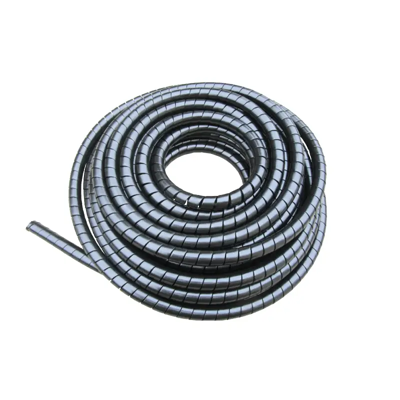
Custom hydraulic hoses meet SAE and EN requirements by matching the hose construction, dimensions, pressure rating, bend radius, temperature range, impulse life, fittings, and assembly process to a published specification. SAE J517:2020 covers common 100R-series hydraulic hoses, while EN families such as EN 853 and EN 856 address wire-braid and spiral-wire designs. A 1/2-inch EN 853 2SN hose, for example, is commonly rated around 275 bar working pressure and 1,100 bar minimum burst pressure. Qualification also covers repeated pressure cycling rather than static pressure alone, so compliance depends on the finished hose-and-fitting assembly, not only the markings printed on bulk hose.
SAE J517 provides general, dimensional, and performance requirements for hydraulic hoses used on mobile and stationary equipment. The current SAE Mobilus listing identifies J517_202007, published in 2020, and states that an assembly using J517 hose and SAE connectors cannot carry a maximum working-pressure rating above the lower-rated component. A 4,000 psi hose connected to a fitting rated for 3,000 psi therefore remains a 3,000 psi assembly.
That component rule leads directly to hose construction. A steel braided hydraulic hose usually uses one or two layers of high-tensile steel wire around an oil-resistant synthetic-rubber tube. EN 853 2SN and SAE 100R2-type products commonly use two wire braids; a published 2025 2SN/R2AT range lists working pressures from about 400 bar for 1/4-inch hose to 80 bar for 2-inch hose. Pressure capacity falls as bore size rises because a larger internal area places greater force on the reinforcement.
Dimensions therefore cannot be treated as nominal labels alone. Published EN 853 2SN data show a nominal 3/8-inch hose with about 9.9 mm inside diameter, 18.4 mm outside diameter, 330 bar working pressure, and a 125 mm minimum bend radius. A 1-inch version rises to roughly 26.0 mm ID and 37.1 mm OD, while working pressure falls to 165 bar and minimum bend radius increases to 300 mm. Those differences affect fitting geometry, routing space, flow velocity, and crimp compression at the same time.
| Typical EN 853 2SN size | Working pressure | Test pressure | Minimum burst pressure | Bend radius |
|---|---|---|---|---|
| 1/4 in | 400 bar | 800 bar | 1,600 bar | 100 mm |
| 3/8 in | 330 bar | 660 bar | 1,320 bar | 125 mm |
| 1/2 in | 275 bar | 550 bar | 1,100 bar | 180 mm |
| 3/4 in | 215 bar | 430 bar | 860 bar | 240 mm |
| 1 in | 165 bar | 330 bar | 660 bar | 300 mm |
The table shows a common 4:1 relationship between working and minimum burst pressure in the cited 2SN range, while test pressure is 200% of working pressure. A 1/2-inch hose rated at 275 bar, for instance, is listed at 550 bar test pressure and 1,100 bar burst pressure. Burst pressure is not an operating allowance; running a system near 1,100 bar because the hose survived a destructive test would ignore the 275 bar working limit.
Static strength covers only part of qualification, which is why pressure-cycle testing follows. EN 856:2015 required 4SP and 4SH spiral hoses to withstand at least 400,000 impulse cycles at 133% of maximum working pressure and 100°C. R12 hoses were specified for at least 500,000 cycles at 133% and 120°C, while R13 used 500,000 cycles at 120% of working pressure. No leakage or other malfunction was permitted before the required cycle count.
A hose can pass a high-pressure burst test and still perform poorly under repeated pressure pulses. One published EN 853 2SN/SAE 100R2AT product specifies 200,000 impulse cycles and reports testing to 400,000 cycles, while another commercial 2-wire hose reports 600,000 cycles. Cycle count should therefore be compared together with test pressure, oil temperature, bend condition, and hose size rather than treated as a stand-alone life estimate.
Repeated cycling also places stress on bends. If a 3/4-inch EN 853 2SN hose requires a 240 mm minimum bend radius, routing it around a 150 mm radius can flatten the tube and change the wire geometry even when system pressure remains below its 215 bar rating. Larger sizes need more room; the cited 2SN data increase from 100 mm minimum radius at 1/4 inch to 420 mm at 1-1/4 inch. Installation layout must therefore be checked before assembly length is fixed.
Bend limits then connect to temperature because rubber stiffness and aging change with heat. ISO 1436:2026 specifies wire-braid hydraulic hose applications with selected oil-based fluids from -40°C to +100°C, water-based fluids from -40°C to +70°C, and water from 0°C to +70°C. A hose routed beside an engine or hot process line must be selected using the temperature at the hose surface and fluid, not simply the general ambient temperature around the machine.
Spiral hose requirements also changed recently. EN 856:2026, dated April 22, 2026, covers four rubber-covered spiral-wire types—4SP, 4SH, R13, and R15—from nominal bore 6 to 51. Its published scope gives -40°C to +100°C for 4SP and 4SH with specified hydraulic fluids and -40°C to +120°C for R13 and R15; water-based fluid service is generally limited to +70°C. A specification sheet based only on an older EN edition should therefore be checked against the edition required by the purchase contract.
Fluid compatibility comes next because pressure qualification does not make every rubber compound suitable for every medium. ISO 1436:2026 names oil-based fluid categories HH, HL, HM, HR, and HV plus several water-based categories, but the actual hose manufacturer's compatibility information still matters. A petroleum-oil hose operated at 100°C with a different synthetic fluid can age differently from the same hose carrying HM mineral oil at 60°C, even when both systems run at 200 bar.
Once the correct hose is selected, fitting compatibility becomes a separate engineering check. SAE J517 states that the rated assembly pressure cannot exceed the lower SAE rating of its hose or connector. Crimping must also follow the validated combination of hose, stem, ferrule, tooling, insertion depth, and final crimp diameter; a fitting with the right 1/2-inch connection thread is not automatically compatible with every 1/2-inch hose.
A production check normally covers four measurable items:
-
Confirm hose ID, OD, specification, batch identity, and required working pressure before cutting.
-
Cut the hose square, remove internal debris, insert the specified fitting to its controlled depth, and use the approved crimp setting.
-
Measure finished crimp diameter with calibrated equipment rather than relying on appearance; manufacturing records should identify the hose and fitting combination used in 100% of assemblies where full traceability is required.
-
Apply proof-pressure testing when required by the customer, standard, or quality plan, then inspect for leakage, fitting movement, blistering, or permanent deformation.
Proof testing should not be confused with burst qualification. The published EN 853 2SN example shows why: its 3/8-inch hose is listed at 330 bar working pressure, 660 bar test pressure, and 1,320 bar minimum burst pressure. Test pressure is high enough to expose assembly problems without intentionally destroying an acceptable hose, whereas burst testing continues into the destructive range and is normally performed on qualification or audit samples rather than every finished production assembly.
Cleanliness matters after cutting because wire-reinforced hose can release rubber and metallic particles into the bore. In hydraulic equipment using close-clearance valves, the assembly process may include compressed-air projectiles or another documented cleaning method before both ends are capped. A 2026-compliant hose contaminated during fabrication can still damage equipment even though its pressure, dimensional, and temperature properties meet the specification, so cleanliness requirements should appear on the purchase drawing when contamination limits are controlled.
Traceability supports the same manufacturing control. A production record can identify the standard edition, hose manufacturer, type, nominal bore, production lot, fitting part numbers, crimp setting, measured diameter, assembly length, manufacturing date, and pressure-test result. When EN 856 moved to a 2026 edition, retaining the applicable edition became especially useful because a customer order referring to EN 856:2015 and one referring to EN 856:2026 are not automatically the same technical requirement.
For procurement, the useful comparison is therefore numerical rather than based on labels such as “high pressure.” A buyer can specify 1/2-inch ID, 275 bar continuous service, -40°C to +100°C oil temperature, 180 mm or smaller permitted routing radius, a required connection type, assembly length tolerance, and the applicable SAE or EN edition. The supplier can then confirm whether a 2SN/100R2-style construction is suitable or whether a compact braid or spiral design is required.
SAE and EN markings identify a performance class, but they do not remove the need to check the finished assembly. A hose rated for 400 bar, a fitting rated for 350 bar, and an adapter rated for 315 bar form a system limited to 315 bar. The same approach applies to temperature, fluid compatibility, bend radius, and connection geometry: the lowest applicable limit governs the installed assembly. SAE J517 expressly applies that lower-rating principle to hose-and-connector working pressure.